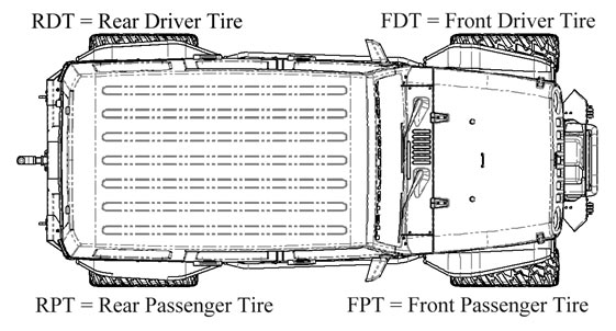

Corner Travel IndexSince 2014, we've traveled 47 states documenting over 10,000 Suspension tests and helping thousands of Jeep owners with their rigs.And we've learned a thing or two along the way. Each day, our engineers apply that unique knowledge to your proven suspension design.The results speak for themselves. 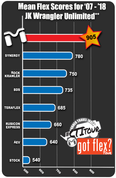 ** Results Based on Mean Corner Travel Index Scores Documented and Recorded over 36 months (2014 - 2017) at events across the United States. -- Sample Set Refined as '07-'17 JK Wrangler 4-Door Non-Rubicon with 3.5" Production Mid Arm Suspension or Lift Kit. -- Population of Sample Set Derived 3000 Tests That Included 1427 JK Wranglers -- 3000 Tests included 1427 JKs, 851 TJs and 455 others. The graph above is just a sampling of the data that we have collected and will be publishing in an updated website at CornerTravelIndex.com -- the site is currently under construction but will allow users to see the builds associated with the various CTI scores and add their own scores under their account. What is Corner Travel Index?Corner Travel Index or CTI measures a vehicle's maximum axle/wheel articulation at the four corners of the vehicle, often referred to as flex. The CTI is used in the off-roading industry to quantify the axle/wheel articulation in order to compare the performance potential of a wide variety of vehicles and vehicle builds. CTI totals the articulated wheel travel of each individual tire on the vehicle (in inches) and multiplies that total by 10 (ten). Significance of CTI and Axle/Wheel ArticulationA vehicle with a higher CTI offers greater axle/wheel articulation and therefore greater potential off-road performance over extreme terrain and obstacles. A vehicle with a higher CTI will maintain more constant wheel contact with the ground while traveling over extreme terrain and obstacles. This ensures that all wheels deliver torque or traction to the ground surface maintaining the vehicles ability to move. Measuring and Calculating CTICTI can be measured two ways, the two wheel method (Estimated) and the four wheel method (Certified). Estimated is the easier value to generate as it only requires lifting the vehicle once. Certified is required and preferred for a truly accurate measurement of the CTI. Calculations use the following tire positions:
Procedure1. Set all tire pressures to 15 psi. This sets a standard for consistent measurement across a wide variety of vehicles and builds. 2. Simultaneously lift the Front Passenger Tire (FPT) and the Rear Driver Tire (RDT) off the ground and STOP lifting when the first tire not being lifted is just about to leave the ground (two tires must be touching the ground). This can be done with forklifts or with a CTI platform lift system. Measure the vertical clearance, in inches, between the ground and the lowest point of the Front Passenger Tire. Measure the vertical clearance, in inches between the ground and the lowest point of the Rear Driver Tire. Measurement must be taken from the lowest point of the tire. Record the values:
3. The two wheel method or Estimate of CTI can be calculated at this time:
4. Simultaneously lift the Front Driver Tire (FDT) and the Rear Passenger Tire (RPT) off the ground and STOP lifting when the first tire not being lifted is just about to leave the ground (two tires must be touching the ground). This can be done with forklifts or with a CTI platform lift system. Measure the vertical clearance, in inches, between the ground and the lowest point of the Front Driver Tire (FDT). Measure the vertical clearance, in inches, between the ground and the lowest point of the Rear Passenger Tire (RPT). Measurement must be taken from the lowest point of the tire. Record the values:
Corner Travel Index (CTI) vs Ramp Travel Index (RTI)The Corner Travel Index (CTI) originated as an alternative to the complex, confusing and inconsistent system known as the Ramp travel index. As off-road enthusiasts looked for better and more consistent ways of measuring axle/wheel articulation it became clear that the CTI was far superior to RTI for the reasons outlined in the side by side comparison below.
|